Electroblock 1.6
The GDLfragments Electroblock 1.6 Library contains a set of objects that allows you to quickly execute plans for installing wiring accessories and devices and at the same time get a high-quality 3D model. Attention is given to form schedules, specifications and pricing.
- Published : August 1, 2018
- Data type : Win, macOS .zip-archive with .lcf-container/Archicad 22—29
- License : Commercial
Electroblock 1.6
46 EUR
Technical details
— You can test some library functions in the workflow using free Electroblock version 1.4
— The Sockets and Switches object creates wiring devices with a different number of items (1-5 mechanisms). The device can be placed both horizontally and vertically. You can have any tilt angle of the object.
— All the GDLfragments Electroblock Library Parts use the value of ID as the Marker value and show in the top line of the Marker. Symbol sizes are configured via the User Interface and are defined in millimeters of the model, regardless of the scale of the Plan.
— The objects Sockets and Switches, Intercom, Wire Output, Ventilator, Bell use the value Base height as the mounting level and show it in the bottom line of the Marker.
— The Sockets and Switches libpart with multiple items automatically generates a composite 2D symbol, depending on the types of its constituent mechanisms. The symbol has its own settings for the size and pens. The placement of the symbol on the Plan can be edited by hotspots, but the Base Point of the electrical block shows the actual location of the device. The Base Point can be both the center of the first unit,- and the center of the electric device. When the frame is vertically positioned, the Base Point is in the center of the top or bottom insert.
— The additional objectsMy mechanism and My 2d-symbol are utilities that serve as a basis for creating your Custom objects. The object ‘My mechanism’ is converted into a morph and the Custom 3d.gsm file is created on its basis. The object My 2d-symbol after the Decomposition / Ctrl + = is converted to 2d primitives, placed on the Project Zero (x: 0; y: 0), and Custom 2d.gsm file is created on its basis.
New in ‘GDLfragments Electroblock 1.6’
Common Functions
— to the Sockets and Switches Object the ability to selectively base the device in the geometric center or in the center of the first accessory / mechanism has been added;
— IP selection has been extended: 20, 22, 23, 43, 44, 55, 65;
— the ability to select the type of device (standard recessed module or special) and additional mechanisms has been added;
— the ability to name accessories / mechanisms at their own discretion has been added. For example: Socket with earthing can be renamed asSocket 220V etc.;
— the ability to create Custom mechanisms and connect them to the device has been added;
— the ability to create Custom 2d-symbols and connect it to the common symbol of the devicehas been added;
2D
— correct display of symbols regardless of the mirror(or not) representation of the object. For example: symbols based on the switch symbol have a slope to the right side, regardless of whether the object is mirrored or not. This function works on the plan and in schedules
— the baseline and the symbol connection line are automatically hidden depending on the distance to the Base Point. The minimal distance at which lines are displayed is configured in the Parameter list
— the ability to change the contents of the subscript text in the Marker has been added: Mounting height, Custom, None;
— on / off display of the baseline in schedules;
— on / off display of the base point,- baseline and symbol connection line on Plan, regardless of the position of the symbol
3D
— Hotspots around the perimeter have been added for dimension binding and in the geometric center of the object. Hotpots support dynamic dimentioning when moving a device.
Schedules and specifications
— The ability to select the display the symbol without a marker and connecting lines, or the front view in schedules
— Output of the frame position type in the schedule (Horizontal / vertical / special frame)
— Set of ready-to-use and configured schedules in folder “Electroblock. Schedules of Elements”:
— A new tab Parameters of mechanisms for calculations organizes the format of the Components of an electric device (Mechanism, Frame, Box) for output to the specification and calculation of quantities and prices in both ARCHICAD environment and export to Excel and Google Sheets
New Library Parts
-
Intercom (Video intercom, Video-call panel, Audio intercom, Audio-call panel)
-
Ventilator
-
Bell
-
Wire output
-
3 types of symbols
-
customizable symbol display in Sections and 3D view
-
a special marker for specifying the length of the output
Accessories and Library Parts
version 1.6
1-gang Switch
1-gang Switch with indicator light
1-gang Two-way Switch
1-gang Two-way Switch with indicator light
Cross Switch
Cross Switch with indicator light
2-gang Switch
2-gang Switch with indicator light
2-gang Two-way Switch
2-gang Two-way Switch with indicator light
3-gang Switch
3-gang Switch with indicator light
Dimmer Switch
Dimmer Switch with indicator light
Sensor Switch
Socket with earthing
Socket with Cover
Internet and LAN Socket
TV Socket
TV-R Socket
TV-INT Socket
RCA Audio/Video Socket
RJ 45 Internet Socket
RJ 11 Telephone Socket
RJ 11 Telephone Socket x2
Floor Heating Thermostat
Room Thermostat
Motion Sensor
Loudspeaker
USB Socket
USBx2 Socket
HDMI Socket
Audio Socket
Audio Socket x2
Audio Socket x4
Contactless Switch
Socket Simple
Push Button Switch
Wire Outlet
Blank Cover Plate
4-gang Switch
4-gang Switch with indicator light
5-gang Switch
5-gang Switch with indicator light
6-gang Switch
6-gang Switch with indicator light
Room Thermostat programm.
Wi-fi hotspot
Detector
Custom 1
Custom 2
Custom 3
Custom 4
Custom 5
Wiring Output
Heated Floor
Electric Panel
Ventilator
Bell
Intercom
Video Intercom
Video-call Panel
Audio Intercom
Audio-call Panel
Examples of Schedules
You can find them in the “Electroblock. Schedules of Elements” set in the “GDLfragments Electrics” folder. You need to extract the files from the archive with the name of the version of ARCHICAD that you are using. Please see
Installing the Library
Video tutorials on YouTube
*currently available in russian
Install
*recommended workflow for installing the library:
-
Unpack the archive
GDLfragments Electrics 16-25.zipinto the folderGDLfragments Electrics 16-25 -
Replace the entire
GDLfragments Electrics 16-25folder into the ARCHICAD library. It is recommended to move theGDLfragments Electrics 16-25folder to the ARCHICAD folder along a path, for example,C: \ Program Files \ GRAPHISOFT \ ARCHICAD 20 \ ARCHICAD Library 20(Windows) -
Start ARCHICAD.
Also a small note: if you have previously used an object in the project Electrical unit 1.4, then you will no longer need it. That is, Electroblock 1.4 should not be loaded into the project, even if there are already sockets and switches 1.4 - only Electroblock 1.6 is needed, replacements will occur automatically. When using 1.4 and 1.6, unwanted duplicate file names are generated. This is noticeable in the interface in the form of incorrect display of mechanism icons.
Previous versions of the library: Electroblock 1.4
Additional links: Electroblock 1.4, TODO 1.7
Comments
Discussion, bugs, feature requests.
 OBJECTS AND LIBRARIES /
ELECTROBLOCK 1.6


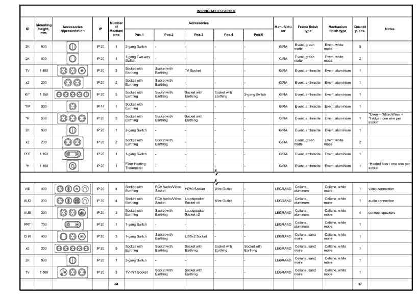 $$
EL-01\ Catalog\ of\ Wiring\ Accessories
$$
$$
EL-01\ Catalog\ of\ Wiring\ Accessories
$$
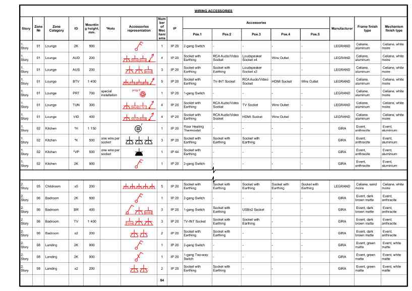 $$
EL-02\ Wiring\ Accessorie\ Schedule
$$
$$
EL-02\ Wiring\ Accessorie\ Schedule
$$
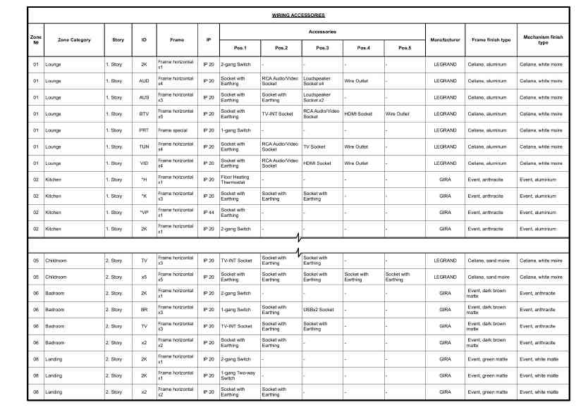 $$
EL-03\ Wiring\ Accessories\ Schedule\ (simple)
$$
$$
EL-03\ Wiring\ Accessories\ Schedule\ (simple)
$$
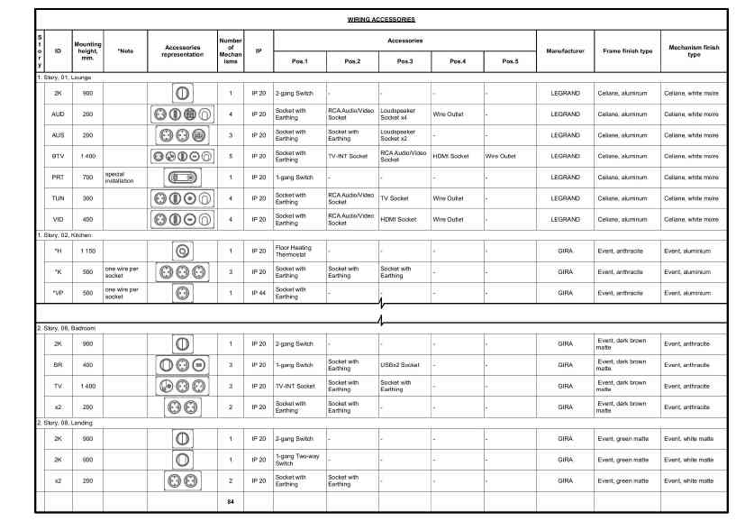 $$
EL-04\ Wiring\ Accessories\ by\ Zones
$$
$$
EL-04\ Wiring\ Accessories\ by\ Zones
$$
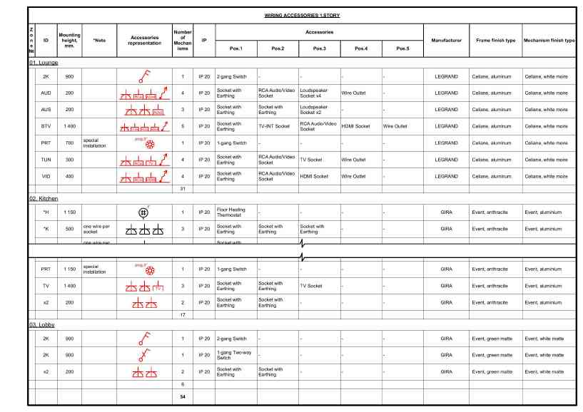 $$
EL-05\ Wiring\ Accessories\ 1.\ Story
$$
$$
EL-05\ Wiring\ Accessories\ 1.\ Story
$$
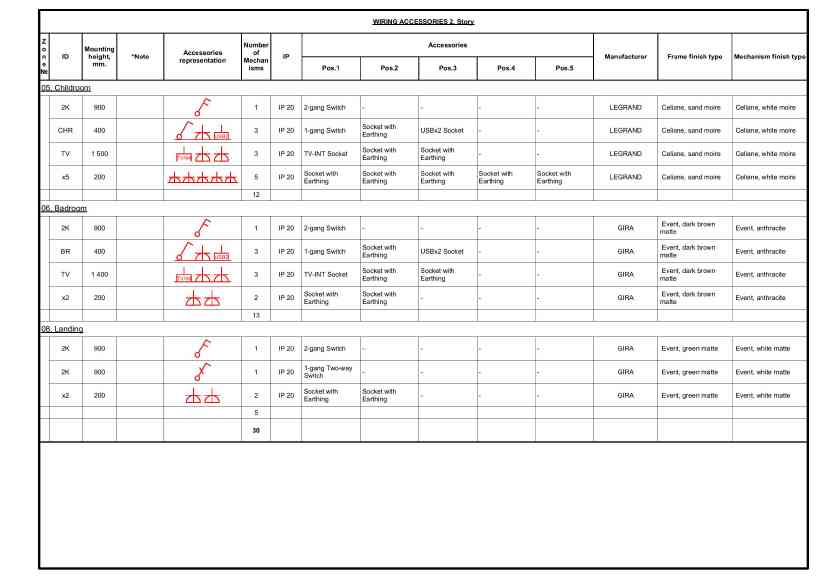 $$
EL-06\ Wiring\ Accessories\ 2.\ Story
$$
$$
EL-06\ Wiring\ Accessories\ 2.\ Story
$$
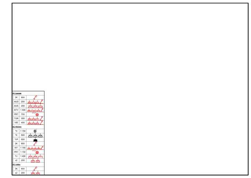 $$
EL-07\ Wiring\ Accessories\ 1.\ Story\ (simple)
$$
$$
EL-07\ Wiring\ Accessories\ 1.\ Story\ (simple)
$$
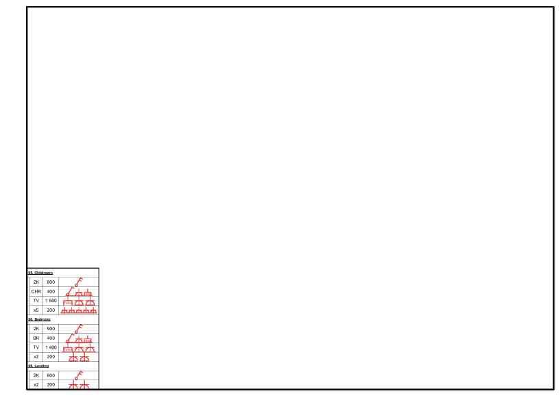 $$
EL-08\ Wiring\ Accessories\ 2.\ Story\ (simple)
$$
$$
EL-08\ Wiring\ Accessories\ 2.\ Story\ (simple)
$$
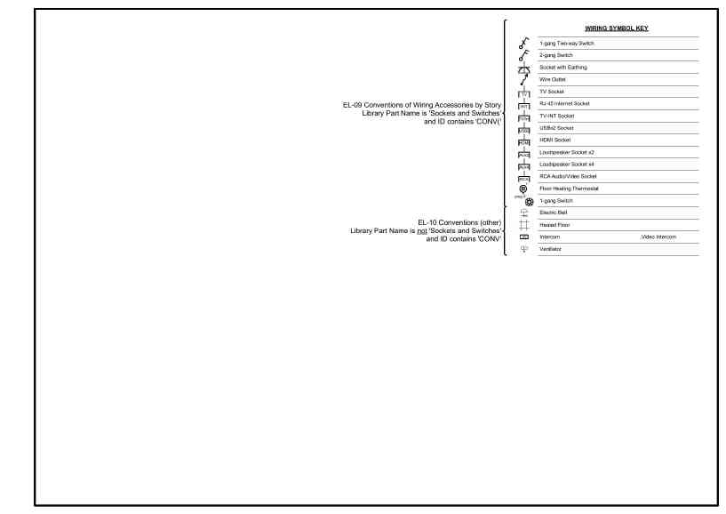 $$
EL-09-10\ Conventions\ of\ Wiring\ Accessories\ by\ Story
$$
$$
EL-09-10\ Conventions\ of\ Wiring\ Accessories\ by\ Story
$$