 OBJECTS AND LIBRARIES /
ELECTRICAL WIRING DEVICES 1.7
OBJECTS AND LIBRARIES /
ELECTRICAL WIRING DEVICES 1.7
Electrical Wiring Devices 1.7
| Technical name ELECTROBLOCK 1.7 is a tool for architects and designers, electricians, and cost estimators working in Archicad®. The library is designed to provide professionals with the most convenient and efficient software solution for implementing project ideas related to electrical systems.
Electrical Wiring Devices 1.7
The library is designed to provide a range of benefits and improvements, such as design convenience and efficiency, accuracy and consistency through sets of Symbols that comply with standards and documentation requirements for electrical installations, as well as improved collaboration and data exchange among different project participants: architects, designers, electricians, cost estimators, and engineers can use the same library, which promotes more effective collaboration, eliminates inconsistencies, and ensures a single, unified source of data for the electrical systems within the project.
The history of the development and distribution of electric power across different countries has led to the emergence of many different standards for models of electrical wiring devices and their representation on architectural plans. GDLfragments has undertaken an effort to analyze and describe the full range of standards currently in use—both for product models and for drawing symbols—in order to identify and unify their common aspects. The Electrical Wiring Devices 1.7 library is presented in configurations that generalize these historically established differences in standards:
IEC

International standards from Europe and many other countries are used as a general reference.
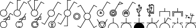
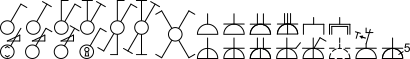
- Names of Electrical Wiring Devices and their graphical symbols (Symbols) based on IEC 606171. General view of a customizable symbol set: switches, dimmers, certain types of power and telecommunication sockets
 ,
,
pole designation , text
  , other equipment and devices
  , indicator (lamp)
  , 180° rotated symbols (Type C)
  , reduced-size symbols
 , and rotated reduced-size symbols
 IEC group symbols, G(GOST) group symbols
 - Enclosure classification according to IP rating based on IEC 605292.
- By default, settings use: modular frame with a 71 mm cell pitch, for flush mounting – standard junction boxes ⌀68×45 mm, for surface mounting – a single box shaped according to the contour of the enclosure.
- The package includes the following standard types of power socket connectors, permitted for use in various European countries and worldwide depending on national standards: Types of Two-Pole Power Sockets
C
 ,
A/C
,
A/C
 ,
E FR
,
E FR
 ,
F DE
,
F DE
 ,
H IL
,
H IL
 ,
J CH
,
J CH
 ,
,
K DK
 ,
L IT,CL
,
L IT,CL
 ,
L 10/16A IT
,
L 10/16A IT
 ,
N BR,ZA
,
N BR,ZA

GOST

Standards of the CIS countries that use SNiP and GOST standards. Also included as part of the IEC set.
- Names of Electrical Wiring Devices and their graphical symbols (Symbols) based on GOST 21.2103. General view of a customizable symbol set: switches, dimmers, certain types of power and telecommunication sockets. The standard provides for specifying the type of mounting, either surface-mounted or flush-mounted.
 ,
,
pole designation, text , other equipment and devices  , indicator (lamp, luminaire, LED backlight) G(GOST) group symbols
- Enclosure classification according to IP rating based on GOST 142542.
- The package includes the following standard types of power socket connectors: Types of Two-Pole Power Sockets
C
F
![]()
GOST
Standards of the CIS countries that use SNiPs and GOSTs are also included as part of the IEC set.
AMS IN DEVELOPMENT

Set based on the standards of North American countries, South American countries, and Japan.
![]()


AMS IN DEVELOPMENT
Set based on the standards of North American countries, South American countries, and Japan


WORLD IN DEVELOPMENT
— full version of the library, which currently includes IEC, the American AMS set, British BS, Australasian AS/NZS, and GOST standards
A, B, C, A/C, D, E FR, F, G UK, H IL, I, J CH, K DK, L IT,CL, L 10/16A IT, M, N BR,ZA, O.
New Features of Electrical Wiring Devices 1.7
General Functions
— Create wiring device models of any shape using parameters and/or connections with external files.
— Display of symbols based on drawing assignment (Power socket outlet layout, Switch layout, etc.) via MVO (Model View Options).
— The product model optionally consists of a plate (frame, shell, etc.), mechanisms, and a mounting box.
— The number of mechanisms has been increased; the product may contain from 1 to 7 mechanisms.
— Placement of mechanisms sequentially without intervals in a single designated compartment (Italian standard).
— Product model depending on the plate structure (frames, casings, panels, blocks, etc.).
— Product model depending on the installation method (surface or flush mounting).
— Naming depends on the specified component composition for Component Lists or Schedules.
— Height anchor offset relative to the home story (finished floor level, half floors, podiums, etc.).
— 3D View on Plan displayed at Plan scale (Model Size) or unscaled (Paper Size).
— Subtype: Wiring Device Component (gdlfragments).
— Subtype: Electrical Symbol (gdlfragments).
— Compatibility with Electroblock 1.6.
— All Electroblock 1.6 models are compatible with Wiring Devices 1.7.
Plate (frame, receptacle, panel, block, etc.)
— Edit plate names via data tables or individually.
— Plate geometry configuration by specifying the geometric structure type:
■ Modular: modular cells with sequential arrangement and fixed pitch.
■ Special: a single unified cell for installing multiple devices or one special device.
■ Irregular: cells of arbitrary size with arbitrary placement.
■ Solid: a monolithic cover panel without cells.
— Select horizontal or vertical plate orientation.
— Automatic indication of plate dimensions for Component Lists or Schedules.
— Select measurement units for plate dimensions.
— Quick plate setup via Data Tables.
— Set up plate geometry of any shape via parameters.
— Quick setup of plate dimensions using Graphical Editing on the Plan.
— Quick setup of plate dimensions using hotspots in 3D view.
— Symmetrical or asymmetrical shape.
— Vertical and horizontal chamfer setup via parameters.
— Special setup of side horizontal chamfers.
— Plate shape end trimming via parameters.
— Selection and setup of decorative insert types.
— Texts on the device surface.
Cells
— Placement of cells according to selected Device type and Plate structure.
— Horizontal and vertical cell spacing for modular devices.
— Cell size adjustment (including irregular cells) via parameters.
— Quick cell size adjustment using Graphical Editing on the Plan.
— Quick cell size adjustment using 3D hotspots.
— Show/hide cell edge between plate and mechanism.
Mechanisms
— Extended built-in mechanisms list. Wiring Devices 1.7 Mechanisms List
— Dedicated interfaces for each built-in mechanism.
— Switch mechanisms: selection and configuration of switch type.
— Power socket mechanisms: selection and configuration of connector type. Supported Power Socket Types in Wiring Devices 1.7
— Mechanisms with indicators: selection and configuration of indicator type.
— USB mechanisms: Type A and Type C support.
— Edit mechanism names via lists or individually.
— Link external models to each mechanism via lists or individually.
Mounting Box (back box, cable duct, etc.)
— Edit mounting box names via lists or individually.
— Automatic mounting box dimensions for Component Lists and Schedules.
— Selectable dimension units for mounting boxes.
— Parameter-based configuration of mounting box geometry (any shape).
— Quick setup by preset size:
■ Modular mounting boxes
■ Single mounting box for modules
■ Enclosure-based box shape and size
■ Box size with housing contour offset
■ Custom mounting box size
Symbols
— Plan-scaled (Model Size) or unscaled (Paper Size) symbols.
— Smart scaling of required 2D elements only.
— Standards-based symbol sets with creation, editing, and assignment.
— Automatic symbol switching for surface or flush installation.
— Mechanisms and symbols organized into functional groups.
— Group-based symbol visibility via Model View Parameters.
— Adjustable symbol spacing.
— Adjustable offset to symbol baseline.
— Vertical symbol placement via parameters or graphical editing.
— Symbol text display and editing.
— Replace symbol group with a single common symbol.
— Selectable connection line type (straight, spline, stepped).
— Optional connection line from base point to each symbol.
— Automatic per-symbol connection lines when groups are hidden.
Label
— Label scaled with Plan (Model Size) or unscaled (Paper Size).
— Extended list of displayable values for label line and subline.
— Selectable elevation units: m, cm, mm, feet, inches.
— Selectable precision for elevation values.
— Selectable fractional increments for feet and inches.
3D View on Plan
— Scales with Plan (Model Size) or remains unscaled (Paper Size).
— Selectable and configurable projection display method.
— Selectable and configurable projection view type.
— Independent level of detail control.
— Show/hide model elements (Plate, Mechanisms, Mounting Box).
Characteristics
— General electrical data for calculations.
— Extended selection of enclosure protection ratings (IP).
— Description of IP rating markings.
— Selection of hatch pens for configurable IP ranges.
Components for Schedules and Lists
— Prices from parameters or Component Data Tables.
— Components: auto-generate component names.
— Components & Prices: auto-generate names with price and calculation.
— Exclude from List (e.g., legend elements).
— Format according to kit composition.
— Price calculation.
— Up to three currencies (main + two additional).
— Component cost calculation in selected currency.
— Optional fixed component cost based on currency rate.
— Calculated total price of the wiring device kit.
Mechanisms and Names
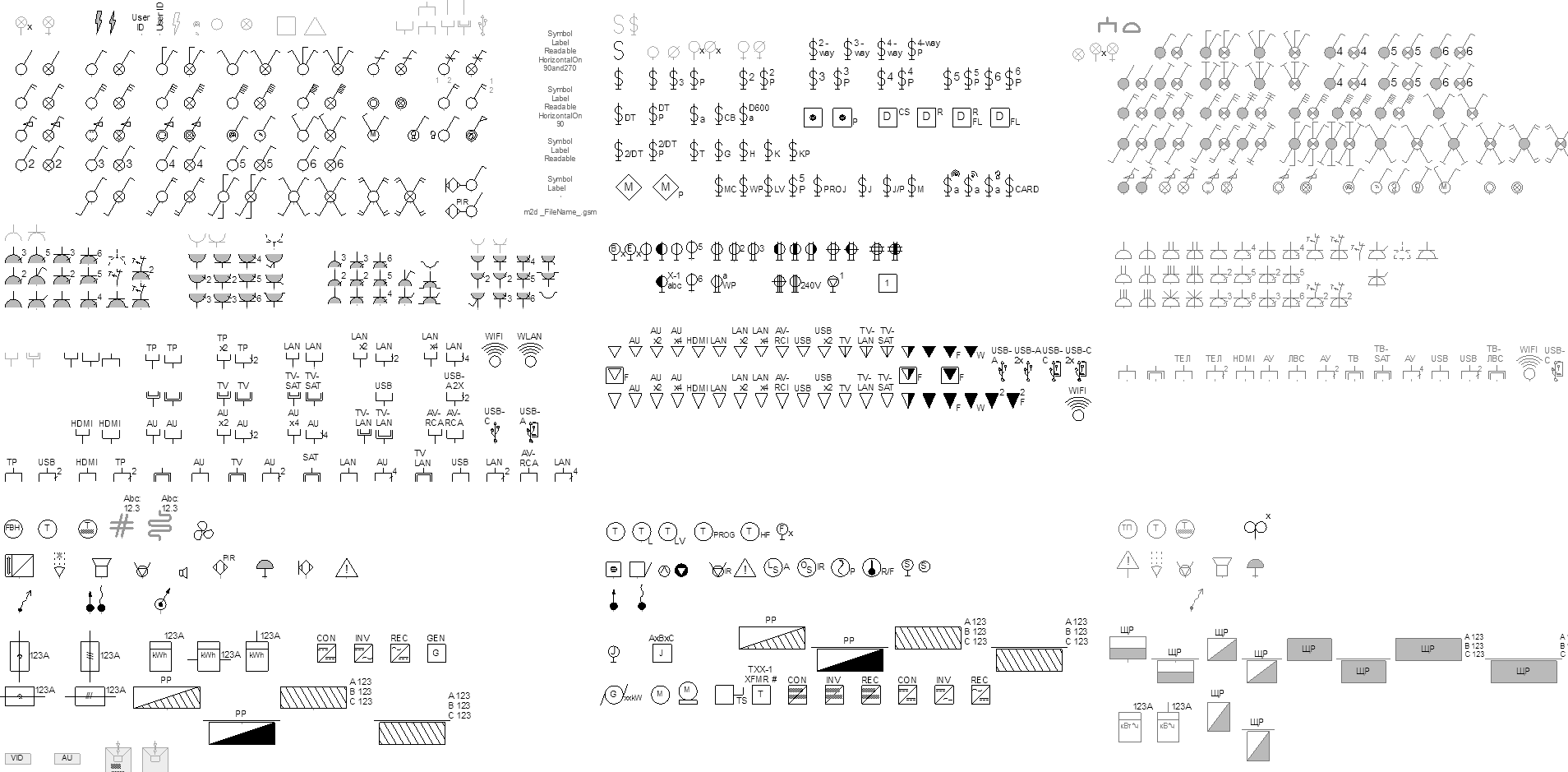
Electrical Symbols
Symbols in the context of the GDLfragments Wiring Devices 1.7 library are a group of .gsm files that the user assigns to each mechanism or device as a general symbol. Depending on the selected mechanism, the “Electrical Wiring Device” object places the corresponding symbols on the plan. Mechanisms can use two symbols: for surface-mounted, and for flush-mounted installations. The switching occurs automatically based on the selected installation type. For convenience, the Symbol Sets by kit and the symbol file index matching tables are provided below, which should be considered when configuring your own symbol sets.
Symbols and Standards
The Wiring Devices 1.7 library provides a set of standard symbols based on the selected package. Users have the option to create custom symbols or symbol sets and link them either through a table or individually. It is highly recommended to familiarize oneself with and utilize the standard symbols, as well as to organize documentation according to established norms. Adhering to these standards during the design phase ensures clarity and consistency in electrical plans, enabling architects, electricians, engineers, and other professionals to easily understand and interpret the plans. This practice guarantees the correct installation and operation of electrical equipment.
Group IEC: electrical symbols based on IEC 60617
The graphical symbols conform to the requirements of the IEC 60617 standard, “Graphical Symbols for Diagrams”, which is widely used in the European Construction Documentation System and in numerous other countries around the world.
Group G: electrical symbols based on GOST 21.210
Graphical symbols comply with the requirements of GOST 21.210—2014
“System of Design Documentation for Construction. Conventional graphical symbols of electrical equipment and wiring on plans”
“System of Design Documentation for Construction. Conventional graphical symbols of electrical equipment and wiring on plans”
Favorites
SHOW / HIDE HELP
For correct loading, display, and operation of the specified Favorites sets, the Wiring Devices object must be included in the Project’s loaded libraries.
-
IEC 60617 “Graphical Symbols for Diagrams" ↩︎
-
IEC 60529 “Degrees of protection provided by enclosures (IP Code)", IEC:IP Code , Wikipedia:IP (Ingress Protection code) ↩︎
-
ГОСТ 21.210 — 2014 Система проектной документации для строительства. Условные графические изображения электрооборудования и проводок на планах ГОСТ 21.210-2014 ↩︎